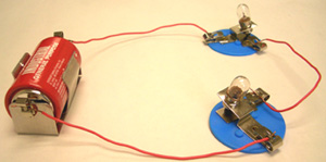
You may have made circuits like this before, using batteries, bulbs, and so on. Recreating a circuit from a picture like this isn't too challenging.

However, sometimes we need to create a more complicated circuit, and trying to do that with a photo can be confusing!
That's why we use circuit symbols and circuit diagrams to represent different electrical circuits. Let's learn about them!
In all of the sciences, we use diagrams to represent ideas. In physics, we use specific symbols to represent components in a circuit. A component is a part of a circuit, like a battery or a bulb.
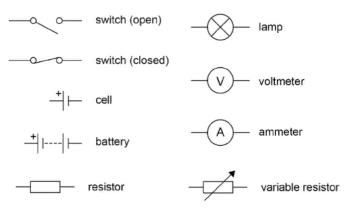
Here is an example. We use this standard symbol for a bulb or lamp:

This symbol is used internationally and will be recognised wherever you are.
There are a lot of standard symbols that we use. Below are some more examples, but this is not a complete list.
To represent a circuit, we put these symbols together to make a circuit diagram. Here is an example.

In this diagram, we can see two cells, an open switch, and a lamp (or bulb). They are connected in one loop.
There are some rules we follow when we draw circuit diagrams so that they are standard and easy to understand.
Firstly, we have represented the wires in the circuit with straight lines. We also use 90-degree angles in the four corners.
Secondly, we always use the standard circuit symbols.
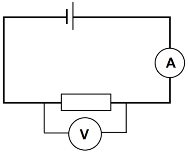
Here is another example. What components are in this circuit?
This circuit has a cell at the top, connected to an ammeter and a resistor.
There is a voltmeter, in its own loop, around the resistor.
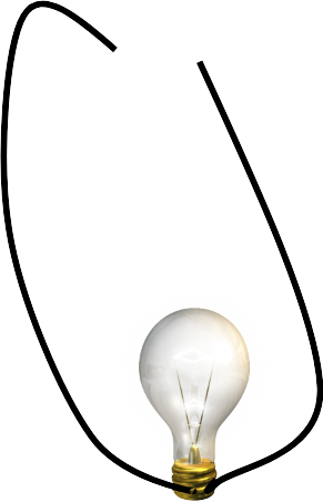
A student has drawn a circuit diagram. What mistakes have they made? Quite a few!

1. They haven't used the correct symbol - they used a picture of a bulb instead.
2. The wires are not straight.
3. The wires do not have 90-degree angles in the corners
4. There appears to be something missing - perhaps a cell or battery.
Now that we have learnt about circuit diagrams, let's check our understanding with some questions!


